 |
|
 |
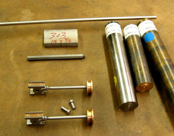
Here's the raw material ... stainless
steal and 936 Bronze. Got these from McMaster Carr. Some time later ...
the parts.
|
|
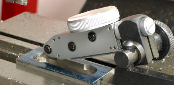
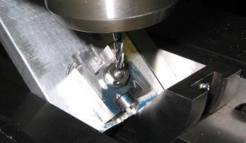
The blank has been machine to the given dimensions for two crossheads.
Here I'm measuring to be sure that the gap for the Main Rod will be
.130". Since the Main Rod has a width of .125" ... there's not much room
for error.
|
 |
|
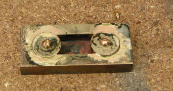 |
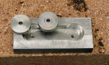
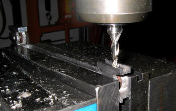
Ready for the plugs to be
silver solder in place. There is a .003" gap for the SS to flow into ...
should be enough.
|
|
Notice that the plugs are little higher than the top surface. This
allowed me plenty of room to get the .360" dimension right on. Next
operation is cleaning up and milling to dimensions. Then cut in half.
|
 |
|
 |
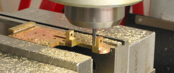
Here is the jig I used to
cut the 8° "wings tips" and the 1/4" radius. To get the 8° I used a 3°
and a 5° angle blocks. Press them against the vice edge to get a snug
fit. Used a cad program to locate the xy coordinates ... drilled then
just moved the x axis. Done! Well had to do that 8 times...
|
|
Now for that 45° cut ...
which is actually a compound cut ... the 45° and the 8°. Again used the
same jig ... set the 8°, tighten the nut then set the 45° and made a
very light cut for the groove.
|
 |
|
 |
Getting close to finishing ... the slipper grooves were next ...set the
endmill in the center took light cuts ... flipped it over and repeated
until the dimension was .703". Notice the crosshead in the background
... need to keep the vice jaws straight.
|
|
I wanted to use Bronze for the slipper, so I made this jig so that the
thickness would be .040" and flat. To do that I faced a piece of round
stock, cut it off for a thickness of about .060", milled the edges down
for a tight groove fit . Then milled the top surface as shown. Finally
sanded the edges for the final .235" dimension.
|
 |
|
 |
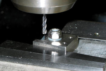
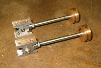
Final product ... need to pin the piston and drill and tap the holes
for the Link Bracket. Kozo's New Shay he uses Loctite on the Pin and Rod
... interesting will have to look into that. I wonder if that helps keep
the steam from leaking thru the gaps.
|
|
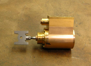
Another look ... the piston is a little tight so I may take a tad
off the piston diameter and a little off the cylinder walls when honing.
If I drop the piston in the cylinder there is no binding. Only when the
rod is attached ... so I guess I have a concentric issue that needs
attention.
|
 |
|
Looking ahead I see that I will soon
be running on air!
|
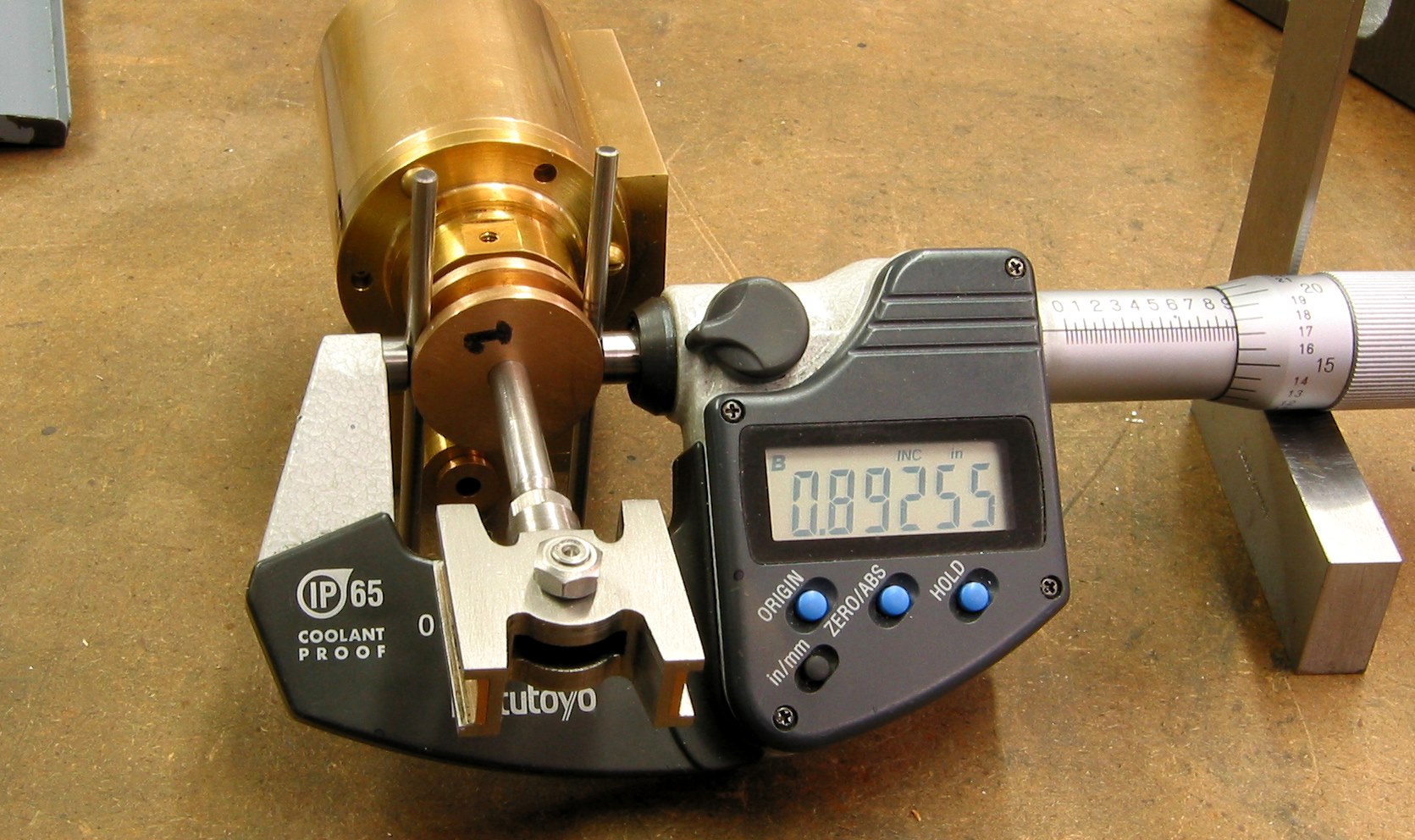
Measuring the gland diameter to get the O-ring squeeze between 5%
and 10%. My final measurement is .8926 - .2050 = .6876 which gives about
a 6.6% squeeze. Of course that assume that the O-ring meets its specs!
|
|
|
Update on the Guide Yoke Assembly (Tie Plate, Guide
Yokes and Guides ) 11/24/2010
These parts were actually easy to machine, of course with the help of
CNC the Tie Plate and Guide Yokes were a piece of cake. CNC is getting
easier with each part. It was the assembling the parts together that was
the real challenge. The Crossheads and Guides are suppose to slide
smoothly over the full stroke.
Wow .... with only a margin of .0025"? Considering that there are so
many parts that are assembled together ... that wasn't going to happen.
Not at least without a few minor adjustments.
I ended up with Guide width of about .231" vs .235" and a Crosshead
groove width of about .244" vs .240". After these changes the parts
would slide somewhat smoothly. I still may need to make additional
adjustments when I run on air. One side was much smoother then the other
... so far I haven't found the part(s) that are causing the problem.
|
 |
|
 |
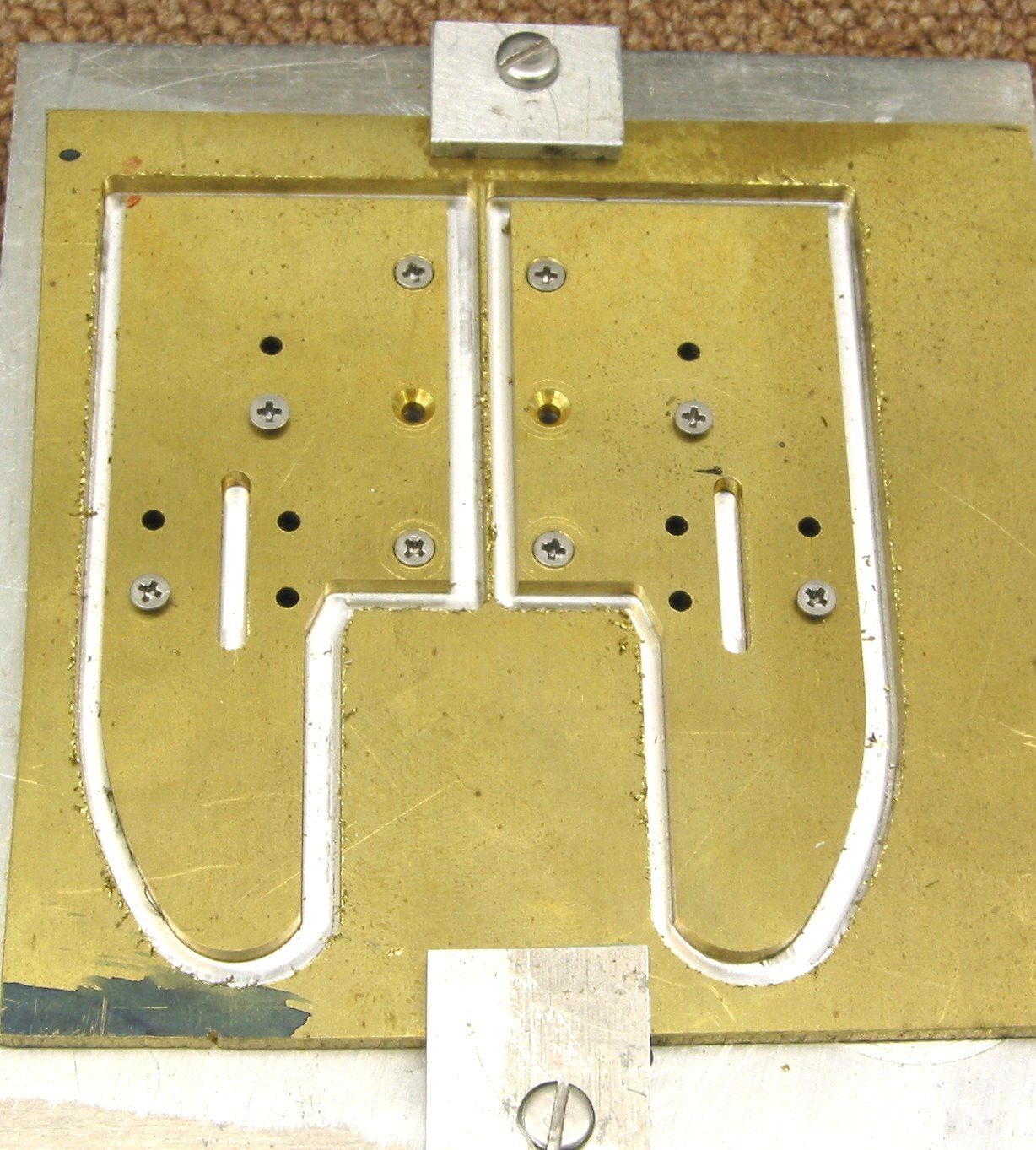
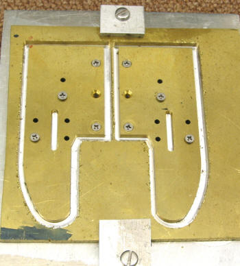
| As you see this is the fixture I used to CNC the Guides Yokes. I put
in a command to stop the process right after drilling the holes so that
I could insert the screws. I used a 1/8" Carbide endmill ... took 6
trips. Total machine time about 15 minutes. Did the Tie Plate the same
... machine time 3 minutes or so. |
|
Back to manual milling. The silver soldering was simple and straight
forward. Cutting the gap was done very slowly with many checks.
|
 |
|
 |
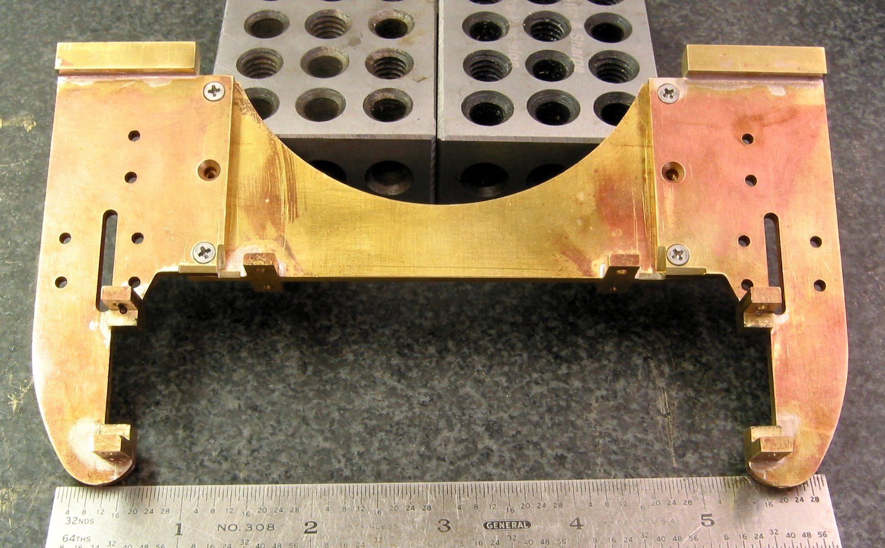
| Guide Yoke Assembly..... If you look closely I added an extra recess
area for the Drive Wheels. |
|
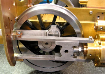
The Guide assembly ...
|
| That's it for now... |